
In our earlier piece titled An Overview of Halbach Arrays, we delved into linear arrays, where magnets are set in a distinct sequence to generate a potent magnetic field on one side. Now, we turn our attention to the circular patterns of Halbach arrays, where the magnets form a ring, resulting in some fascinating outcomes.
The Man Behind the Arrays: Klaus Halbach
During the 1980s at the Lawrence Berkeley National Laboratory, physicist Klaus Halbach became a prominent figure associated with these magnetic structures. He employed these magnet setups to concentrate beams in particle accelerators. Notably, a few years prior, John C. Mallinson had already identified this phenomenon, but it was Halbach’s practical use that solidified his name with the concept.
Curiously, these arrays have garnered attention from those pursuing free energy, magnetic levitation, and methods to circumvent Lenz’s law. In this piece, we aim to shed light on these arrays, emphasizing their tangible and straightforward characteristics.
Magnetic Circles
Various magnet placements lead to diverse circular patterns, each manifesting distinct outcomes. A graphic from Wikipedia showcases four separate patterns. Each pattern correlates with a number, k, spanning from 1 to 4. But what exactly does this ‘k’ signify?
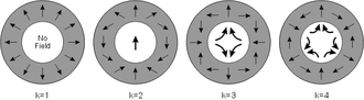
The diagram uses arrows to depict the magnetization direction of 12 magnets arranged in a circle. As you imagine walking around the circle of magnets, each magnet’s orientation rotates by a certain degree. For k=1, the rotation is 360°, matching the circle’s circumference.
With k=2, the magnets rotate twice as fast. As you move 30° around the circle to the next magnet, the magnetization direction has shifted by 60° from the previous one.
Similarly, for k=3, the magnets rotate three times around the circle. Lastly, with k=4, it rotates four times. Essentially, k represents the number of rotations in the magnetization direction as you move around the circle.
What's the Point?
Based on the chosen arrangement, distinct magnetic field intensities and orientations within the circle become evident.
The k=1 configuration appears to have “no magnetic field,” but that’s not entirely accurate. There’s a strong field pointing outward, mimicking a radially magnetized ring. There’s a point at the center where the field strength drops to zero, but elsewhere, some intriguing phenomena occur.
The k=2 setup produces a consistent magnetic field over a large area with minimal variation in strength. This is the configuration we’ll delve deeper into in this article.
The k=3 setup generates what’s known as a quadrupole magnet, where the magnetic field direction passes through four points. The field strength is weakest at the center and grows stronger as you move away. This is invaluable for guiding particle beams, precisely what physicists need!
The k=4 setup is similar but creates a hexapole magnet with six poles. This is also used in particle accelerators for specific tasks like “controlling chromatic aberrations and damping the head tail instability.”
Playing with Uniform Magnetic Fields
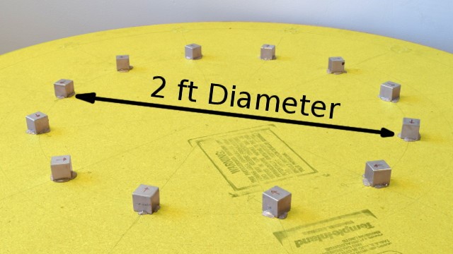
We constructed a k=2 Halbach array using several BX0X0X0-N52, 1-inch cube magnets, arranged in a 2-foot diameter circle. This setup resulted in a magnetic field strength of about 12 gauss at the circle’s center.
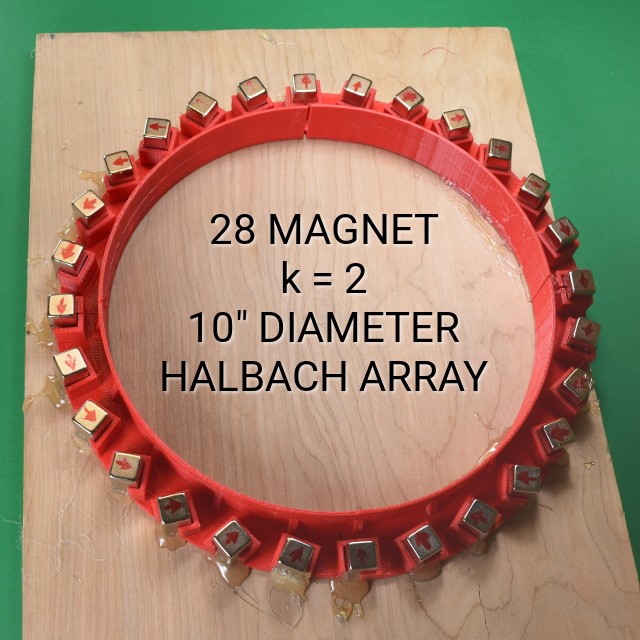
We then created a smaller 10-inch diameter k=2 array using 28 BX088-N52 magnets, each measuring 1″ x ½” x ½”. The center’s magnetic field strength was 73 gauss. More magnets in a smaller ring provide a stronger magnetic field. However, the effects of the uniform field were quite similar.
Adjusting the Strength of Halbach Arrays
The magnetic intensities we’ve highlighted thus far are on the milder side. In certain scenarios, incorporating more magnets or upsizing them, while ensuring they are densely packed, can lead to elevated magnetic field intensities. Crafting such a magnetic assembly might strain the pocket and pose assembly challenges. Yet, when juxtaposed with high-priced electromagnets that demand substantial power, this alternative might emerge superior. These configurations deliver a formidable magnetic field sans any power input.
So, how do individuals tweak the magnetic field intensity of these configurations? Suppose they target a magnetic system of 5,000 gauss but land on figures like 4,975 or 5,050? The key is in employing additional Halbach arrays. By embedding one array inside another, one can either amplify or diminish the field.
For instance, when we integrated the smaller 12 gauss array within the more expansive 73 gauss one, the internal field’s intensity exhibited fluctuations based on their relative rotations. The range could span from a low of 73 – 12 = 61 to a peak of 73 + 12 = 85, or any value within this bracket.
How Do These Magnet Arrays Produce a Uniform Field?
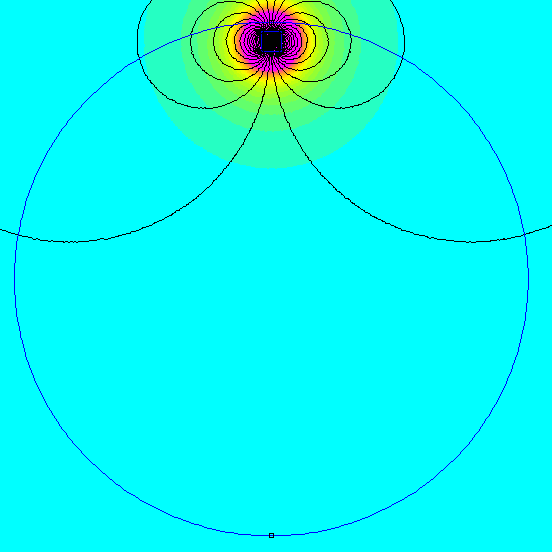
Diving into the mathematics behind this setup reveals a fascinating combination. Each magnet you add to the circumference contributes a certain magnetic field strength at the center, both vertically and horizontally. Interestingly, in this arrangement, all horizontal components tend to cancel each other out. That’s why the magnetic field direction is purely vertical.
On the other hand, each magnet contributes a certain magnetic field strength vertically, all pointing in the same direction. It’s a clever and elegant solution.
An accompanying gif illustrates the magnetic field distribution as magnets are progressively added to the Halbach array.
Dipole Moment Experiments
Let’s delve into an exploration involving a consistent magnetic field. The dipole moment of a magnet serves as a testament to its potency. It provides insights into the rotational force a magnet would undergo when positioned within a uniform magnetic field.
By its very definition, the dipole moment equates to the rotational force experienced by a magnet in a consistent field. The units themselves are revealing: torque for every tesla (representing the magnetic field). Let’s introduce some magnets to this field, gauge the torque, and ascertain if the outcomes resonate with our anticipations!
A side note: In our prior piece, A Guide to Measuring Magnets, we touched upon determining the dipole moment by monitoring the current induced in a coil as a magnet traverses through it. Though that technique boasts greater accuracy, for the context of this article, a direct torque measurement offers a more interactive experience!
Introducing a magnet into the array, and thereby into the potent uniform magnetic field, subjects it to a torque stemming from the magnetic interactions. This phenomenon mirrors the behavior of a compass needle swiveling due to the Earth’s magnetic field, albeit on a much amplified scale. An accompanying visual depicts a 25-cent coin resting atop a BY0X02 block magnet, resisting the torque that endeavors to invert it because of its magnetic moment. In numerous instances, this magnetic rotational force is potent enough to surpass the gravitational tug striving to maintain the magnet’s horizontal orientation.
In Conclusion
Halbach arrays, with their unique configurations and magnetic properties, offer a world of possibilities. From guiding particle beams in accelerators to creating uniform magnetic fields for various applications, their versatility is unmatched. As we’ve seen, understanding their underlying principles can lead to innovative applications and experiments. Whether you’re a physicist, engineer, or just a curious mind, diving into the world of Halbach arrays is sure to be a magnetic attraction!
If you’re considering implementing a Halbach Array for your projects, remember that customization can make all the difference. At EPI Magnets, we specialize in crafting Halbach Arrays tailored to your specific requirements. As industry leaders, we ensure top-tier quality and precision in every product. Feel free to explore our offerings and connect with our team for any inquiries.